


SAE 37° flare flanges are crucial components in hydraulic systems, known for their reliability and efficiency in handling high - pressure fluid transfer. As a well - established supplier of SAE 37° flare flanges, I am often asked about the installation clearances for these flanges. In this blog, I will delve into the key aspects of installation clearances for SAE 37° flare flanges, providing you with comprehensive information to ensure proper installation and optimal performance.
Understanding SAE 37° Flare Flanges
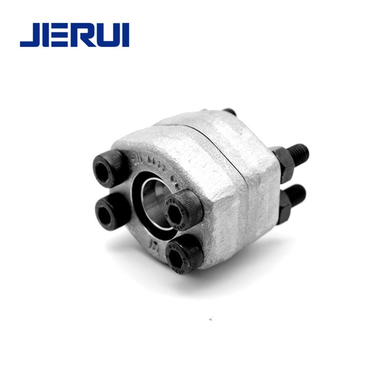
Before discussing the installation clearances, it's essential to understand what SAE 37° flare flanges are. These flanges are designed with a 37 - degree flare angle, which provides a secure and leak - free connection in hydraulic systems. They are commonly used in various applications, including automotive, aerospace, and industrial machinery, due to their ability to withstand high pressures and vibrations.
The 37 Degree Flare Flange is standardized according to SAE (Society of Automotive Engineers) specifications, ensuring compatibility and interchangeability across different systems. The flanges are typically made from high - quality materials such as steel or stainless steel, which offer excellent strength and corrosion resistance.

Importance of Installation Clearances
Installation clearances play a vital role in the proper functioning of SAE 37° flare flanges. Incorrect clearances can lead to a variety of issues, including leaks, reduced system efficiency, and premature component failure. When the clearances are too tight, it can cause excessive stress on the flange and the mating components, leading to deformation or cracking. On the other hand, if the clearances are too large, it can result in loose connections, which may lead to fluid leakage and reduced system performance.
Types of Installation Clearances
Radial Clearance
Radial clearance refers to the space between the outer diameter of the tube and the inner diameter of the flange bore. This clearance is critical for ensuring a proper fit between the tube and the flange. A proper radial clearance allows for easy insertion of the tube into the flange while still providing enough contact area for a secure seal.
The recommended radial clearance for SAE 37° flare flanges typically ranges from 0.05 mm to 0.15 mm, depending on the tube size and the application requirements. For smaller tube sizes, a smaller radial clearance may be required to ensure a tight fit, while larger tube sizes may allow for a slightly larger clearance.
Axial Clearance
Axial clearance is the space between the end of the tube and the face of the flange. This clearance is important for allowing the tube to expand and contract due to temperature changes and pressure variations in the hydraulic system. If the axial clearance is too small, the tube may be restricted from moving, which can cause stress on the flange and the tube, leading to potential failure.
The appropriate axial clearance for SAE 37° flare flanges is usually in the range of 0.5 mm to 1.5 mm. This clearance should be carefully measured and adjusted during the installation process to ensure that the tube has enough room to move freely without causing any damage to the flange or the system.
Flange - to - Flange Clearance
When multiple SAE 37° flare flanges are used in a system, the flange - to - flange clearance is also an important consideration. This clearance refers to the space between the faces of adjacent flanges. A proper flange - to - flange clearance is necessary to prevent interference between the flanges and to allow for easy installation and removal of the flanges.
The recommended flange - to - flange clearance typically ranges from 1 mm to 3 mm. This clearance can be adjusted depending on the specific requirements of the system, such as the need for access to the flanges for maintenance or inspection.
Factors Affecting Installation Clearances
Tube Material and Size
The material and size of the tube have a significant impact on the installation clearances. Different tube materials have different coefficients of thermal expansion, which can affect the axial and radial clearances. For example, aluminum tubes have a higher coefficient of thermal expansion compared to steel tubes, so they may require larger clearances to accommodate the expansion and contraction.
The size of the tube also plays a role in determining the clearances. Larger tubes generally require larger clearances due to their increased mass and potential for greater expansion and contraction.
Operating Conditions
The operating conditions of the hydraulic system, such as temperature, pressure, and vibration, can also affect the installation clearances. High - temperature applications may require larger clearances to allow for thermal expansion of the components. Similarly, high - pressure systems may need tighter clearances to ensure a secure seal and prevent leakage.
Vibration can also cause the components to move and shift, so proper clearances should be provided to prevent excessive stress on the flanges and the tubes.
Measuring and Adjusting Installation Clearances
Accurate measurement of the installation clearances is crucial for ensuring proper installation of SAE 37° flare flanges. Precision measuring tools such as calipers, micrometers, and feeler gauges should be used to measure the radial, axial, and flange - to - flange clearances.
If the measured clearances are not within the recommended range, adjustments can be made. For radial clearances, the tube diameter can be adjusted by using a tube expander or a tube reducer. Axial clearances can be adjusted by trimming the end of the tube or by using spacers. Flange - to - flange clearances can be adjusted by adding or removing shims between the flanges.
Compatibility with Other Components
SAE 37° flare flanges are often used in conjunction with other components in a hydraulic system, such as Steel Tube Assembly and ISO 6164 Flare Flange. It is important to ensure that the installation clearances of the SAE 37° flare flanges are compatible with these other components.
When connecting SAE 37° flare flanges to other types of flanges or components, the clearances should be carefully considered to ensure a proper fit and a leak - free connection. This may require additional adjustments or the use of adapters to achieve the desired clearances.
Installation Best Practices
- Clean Components: Before installation, all components, including the flanges, tubes, and seals, should be thoroughly cleaned to remove any dirt, debris, or contaminants. This helps to ensure a proper seal and prevent damage to the components.
- Use Proper Tools: Use the appropriate tools for installation, such as torque wrenches, tube cutters, and flaring tools. Using the wrong tools can lead to improper installation and damage to the components.
- Follow Manufacturer's Instructions: Always follow the manufacturer's instructions and specifications for installation. This includes the recommended installation clearances, torque values, and assembly procedures.
Conclusion
In conclusion, proper installation clearances are essential for the reliable and efficient operation of SAE 37° flare flanges in hydraulic systems. By understanding the different types of clearances, the factors that affect them, and how to measure and adjust them, you can ensure a successful installation and avoid potential issues such as leaks and component failure.
As a trusted supplier of SAE 37° flare flanges, we are committed to providing high - quality products and comprehensive technical support. If you have any questions about the installation clearances for our SAE 37° flare flanges or need assistance with your hydraulic system, please feel free to contact us for procurement and further discussions. We look forward to working with you to meet your specific needs.
References
- SAE J514 Standard - Flared Fittings for Hydraulic and Pneumatic Fluid Power Systems
- Hydraulic System Design and Installation Manual